|
|
|||||||||||||||||||||||||||||
|
Chemical and Process Engineering |
|||||||||||||||||||||||||||||
|
|
|||||||||||||||||||||||||||||
|
|||||||||||||||||||||||||||||
|
|
|
|
|
|
|||||||||||||||||||||||||
|
Huntsman LDPE
Project |
|||||||||||||||||||||||||||||
|
|
|
|
|
|
|
||||||||||||||||||||||||
|
Low Density Polyethylene |
|
|
|
Client: Simon-Carves |
|||||||||||||||||||||||||
|
|
|
||||||||||||||||||||||||||||
|
2005/6 |
Senior Process Engineer |
||||||||||||||||||||||||||||
|
|
|
||||||||||||||||||||||||||||
|
|
|
||||||||||||||||||||||||||||
|
Project
Background |
|||||||||||||||||||||||||||||
|
|
|
||||||||||||||||||||||||||||
|
SembCorp
Simon-Carves Limited were initially awarded a contract by Huntsman
Petrochemicals UK Ltd (now Sabic), for the front
end engineering design (FEED) of the LDPE process using ExxonMobil’s
technology, They were subsequently awarded a further contract for the
detailed design, supply and construction of this plant at their Wilton
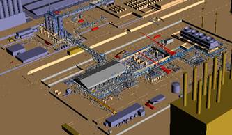
complex in the North East of England. This is the world’s largest single stream LDPE plant, with a total capacity of 400,000 tonnes per year. |
|||||||||||||||||||||||||||||
|
|
|
|
|
|
|
||||||||||||||||||||||||
|
|
|
|
|||||||||||||||||||||||||||
|
Summary
of Process |
|||||||||||||||||||||||||||||
|
|
|||||||||||||||||||||||||||||
|
The process (from ExxonMobil) is based on a high pressure tubular reactor. Ethylene is supplied to the plant and compressed using primary and secondary compressors to a pressure of around 3000 bar. |
|||||||||||||||||||||||||||||
|
|
|
|
|
||||||||||||||||||||||||||
|
Courtesy Simon-Carves |
|
The compressed Ethylene gas is preheated and
passed through a number of tubular reactor zones (total length nearly 3km) into
which organic peroxides, dissolved in a straight chain saturated hydrocarbon,
are injected to initiate the reaction. An unsaturated hydrocarbon can be added to the
ethylene as a modifier to control the melt index. An organic aldehyde can
also be used as a modifier for the production of medium density polyethylene. The reactors are double pipe units with
pressurised hot water flowing in the annuli. The polymerisation reaction is
highly exothermal and the energy removed from the reaction is converted in to
steam at various pressures for use within the LDPE plant and elsewhere on
complex. Excess unused ethylene is separated after the reactors and recycled
to the reactor feed system. The polymer melt is mixed with master-batch additives in an extruder to yield the final product. Some ethylene is carried forward through the extruder and the pellets are degassed with air during intermediate storage prior to being sent to final product storage. |
|||||||||||||||||||||||||||
|
|
|
|
|
||||||||||||||||||||||||||
|
|
|
|
|||||||||||||||||||||||||||
|
Specific
Responsibilities |
|
|
|||||||||||||||||||||||||||
|
|
|
|
|||||||||||||||||||||||||||
|
|||||||||||||||||||||||||||||
|
|
|
|
|
|
|
||||||||||||||||||||||||
|
|
|
|
|
|
|
||||||||||||||||||||||||
|
Pressurised Water System |
|
|
|
|
|
||||||||||||||||||||||||
|
|
|
|
|
|
|
||||||||||||||||||||||||
|
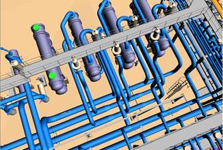
The
purpose of pressurised hot water system is initially to bring the reactor metalwork
up to running temperature and then to remove the immense quantity of heat
generated by the reaction (c 50MW). The system also allows controlled
de-fouling of the reactors. The high operating temperature of the process
requires the water to be pressurised to around 30 barg
to avoid vaporisation occurring especially at the hot reactor walls. This required the specification of pumps, heat exchangers, control valves etc serving 6 reactor reaction zones and associated cooling zones, recycle gas cooling and as well as extrusion temperature control. A 50 m3 expansion drum also formed part of this system. |
Courtesy Simon-Carves |
||||||||||||||||||||||||||||
|
Utility Systems |
|
|
|
|
|
||||||||||||||||||||||||
|
|
|
|
|||||||||||||||||||||||||||
|
The
detailed design of the utility systems covered steam, condensate, cooling
tower water distribution, raw and process water, plant and instrument air,
high and low pressure nitrogen, boiler feed water and silo wash water
systems. For use
within the plant, imported steam (up to 65 barg)
from the Wilton power station is let down to high pressure (32 barg) using enthalpy control. The pressure is then
subsequently let down to medium (10 barg) and low
(3.5 barg) pressures. Condensate
from these systems is recovered at different pressures to minimise the amount
of flash steam formed in the condensate pipe work. The plant
also has steam and condensate switching station to allow the use of either MP
or LP steam for jacketing and tracing. For
operations that produce excess steam, a direct contact condenser was
specified, with the resulting condensate being used as cooling tower make-up
water. The boiler
feed water system required the specification of de-aerator and boiler feed
water pumps. After de-aeration of recovered condensate together with
demineralised water imported from the power station, it is chemically treated
for use in process waste-heat boilers, steam de-super-heaters and for make-up
to closed circuit water systems. Liaison
with the plant Owner was required in relation to battery limit and water
treatment requirements. |
|||||||||||||||||||||||||||||
|
|
|
|
|
|
|
||||||||||||||||||||||||
|
|
|
|
|
|
|
||||||||||||||||||||||||
|
Documents Produced Process
descriptions. Utility demands. P&IDs Control system
narratives. Process calculations
and data sheets for centrifugal and reciprocating pumps, shell and tube heat
exchangers, pressure vessels. Specialist Software "InTools" for creating process specifications for
instrumentation. "PDMS Reality
Review" for 3D plant layout visualisation. "TASC5"
for shell and tube heat exchanger design. |
Instrument data
sheets for pressure, temperature, flow and level transmitters. Specifications for
steam pressure reducing and de-super-heating stations. Calculations in
support of instrument and pressure regulator specifications. Calculations for
pressure drop, line sizing and control valve size checks. Process duty steam trap specifications. |
||||||||||||||||||||||||||||
|
|
|
||||||||||||||||||||||||||||
|
|
|
|
|
|
|
|
|
|
|
|
|
|
|
|
|||||||||||||||